


Overview
In high-voltage, high-speed, and noise-prone environments, traditional differential probes often fail to deliver accurate, safe signal measurements. The RIGOL PIA1000 Series Optical Isolated Probes achieve full electrical isolation through optical transmission, dramatically improving common-mode rejection and measurement precision. This article presents two practical test cases to highlight the superior performance of this solution in GaN and SiC power device applications.
Testing Background and Technical Challenges
Conventional differential probes suffer from several key limitations:
- No electrical isolation, posing safety risks during high-voltage testing;
- Signal degradation due to parasitic capacitance and inductance in cables;
- Long cables act like antennas, introducing noise and oscillation;
- Poor performance in suppressing high-frequency common-mode interference.
While differential probes remain cost-effective and easy to use, they are increasingly unsuitable for modern wide-bandgap device testing involving floating grounds, rapid switching, and wide voltage ranges.
RIGOL’s Solution and Product Advantages
The RIGOL PIA1000 Series Optical Isolated Probes eliminate these drawbacks by converting electrical signals into laser signals, transmitting them through fiber optics, and reconverting them back — ensuring complete isolation between device and scope. Key advantages include:
- Ultra-high CMRR: Up to -180 dB near DC and -108 dB at 1 GHz;
- Excellent isolation voltage: Up to 85 kV depending on system insulation;
- Wide measurement range: Supports low to high differential signals via interchangeable attenuators;
- Optimized connections: MCX/MMCX interfaces minimize cable length and area, reducing noise pickup;
- Ideal for applications such as power supplies, GaN/SiC design, EMI/ESD diagnosis, and floating or high-side measurements.
Step-by-Step Use and Practical Application
Test Case 1: Vgs Signal on GaN Device
1. Connect the attenuation cable to the E-O converter and tighten with the locking nut.
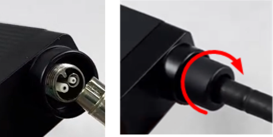
[Image 1: Attenuation Cable Connection]
2. Solder the MCX socket directly to the MOSFET gate (G) with minimal stub length; trim extra pins for easier mounting.
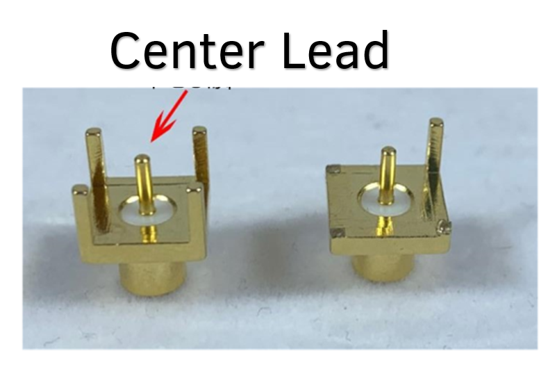
[Image 2: Pin Reduction Illustration]
3. Insert the cable into the socket and ensure a secure "click" connection.
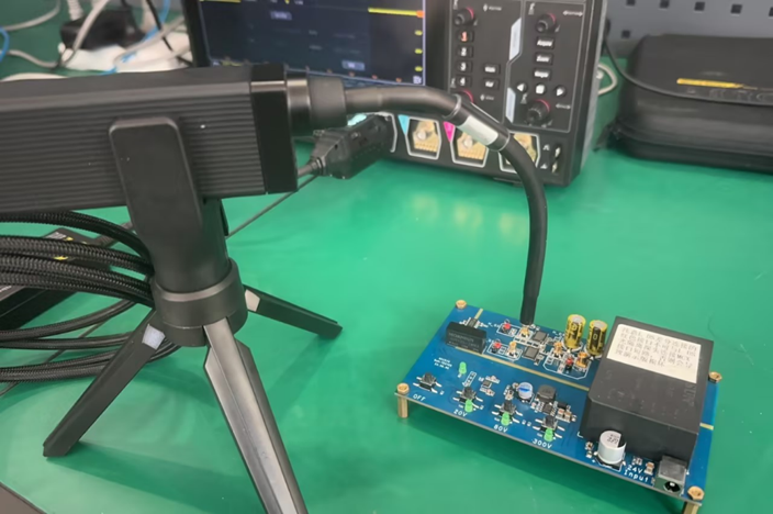
[Image 3: Optical Probe Setup]
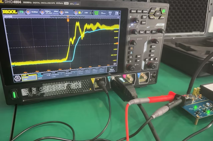
4. Compare results at 20 V common-mode voltage:
- Channel 1 (Yellow, differential probe) shows strong ringing and waveform distortion;
- Channel 2 (Blue, optical probe) reveals a clean, accurate Vgs signal.
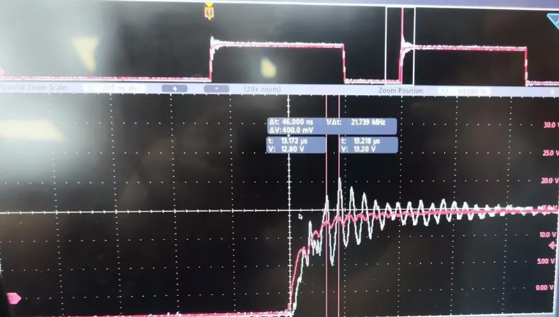
Test Case 2: SiC IGBT Dual-Pulse Measurement
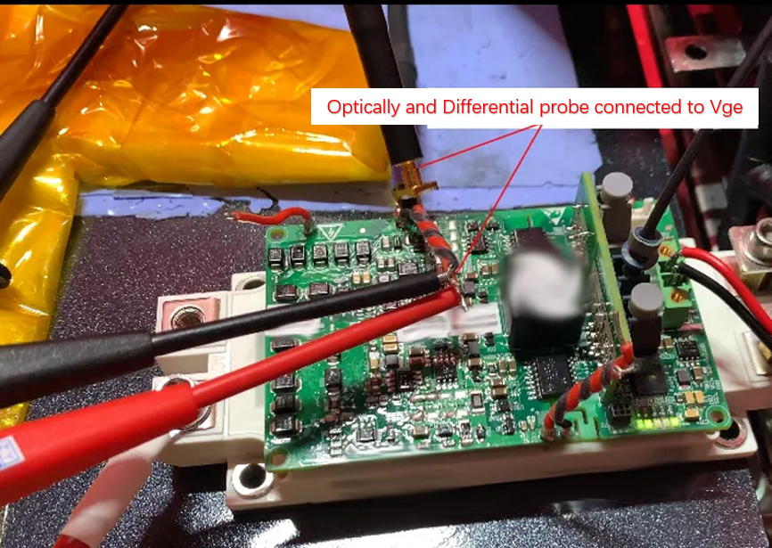
Using a SiC half-bridge test setup (Vce ≈ 500 V), we simultaneously connected both probes to the upper-arm Vge terminal:
- The white trace (differential probe) shows severe oscillation during signal transitions — risking misjudgment in circuit design;
- The red trace (optical probe) maintains clarity and minimal interference — even though some visible noise originates from the differential probe’s crosstalk.
Conclusion and Outlook
Across both real-world examples, the RIGOL PIA1000 Series proves to outperform traditional differential probes in terms of isolation, signal clarity, and noise immunity. For applications involving floating nodes, high-side gate drive, dual-pulse testing, or wide-bandgap semiconductors, this optical probe is the optimal choice for accuracy and safety.
RIGOL will continue expanding its PIA1000 ecosystem through attachments and configuration options — supporting engineers in capturing more reliable, precise, and interference-free high-voltage signals.